-Fixed-Wing UAV Assembly Process-
Introduction:
Assembling a Fixed-Wing UAV airplane model is a learning journey toward real aerospace applications for aerospace engineering students. It is an essential start to do hands-on work to give some tangible feelings of practicality; however, it depends on the level of commitment, discipline style, and the amount of reading relevant topics over the coming years. Hope you will enjoy a different taste in this blog.
Objective:
This post is aimed to show the progress of my contributions to a SKY HUNTER (SKH), UAV, project under University Sains Malaysian, or USM, staff for an industrial application.
Work Flow Begins:
Day 1:
1. Unboxing:
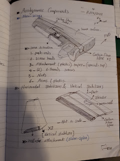
It is important to carefully unbox the UAV parts to avoid damaging the aerodynamic components such as the main wings, fuselage, and the vertical and horizontal stabilizers. Therfore, choosing the correct cutting tool and removing the sides of the box to unload the parts gentally on a clean table. See figure 1.
 |
| Figure 1: The SKH UAV inside the box |
 |
| Figure 2: Using my cutting pen to open the sides of the box |
2. Labeling and Notes Taking:
It depends on the person, this step can be helpful for those who take the time to read a catalog of an RC airplane for instructions and discipline. The parts can be given numbers and short names for easier future tracking, this will help you if you are an aerospace engineer in some of the Aerospace industries. Take notes from previous experts from YouTube or books for easier instructions and techniques in assembly.
3. Parts on a Table! :
 |
Figure 3: Those two brushes of sizes 2 and 8 are to be used for gluing the parts during the assembly of the fuselage, two main wings, and other parts. |
After opening the box correctly, gentally take each part outside on a clean table and make sure they are layed safely to avoid scratching the surfaces of the parts especially the wings.
3. Remarks on Main Wing's mating tolerance:
At this stage, the wings' roots attachment showed 2 mm gaps, which is not prefered during flight and air will go inside the wing box and might cause minor structure damages at high speed. Thus, I had to sand the roots and make sure no gaps are there using sanding sheets and cutting knife. See the photos below.
4. Attachments of vertical and horizontal stabilizers:
|
Day 4:
Tasks:
1. Engine Mount Modifications (Wooden-disk):
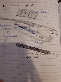
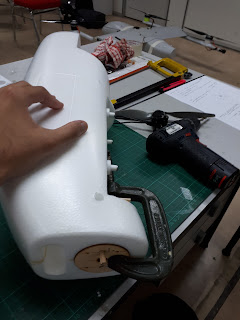
The electrical motor generates certain torque during operations and this will cause a torque load on the engine mount, wooden disk, to rotate. However, to address the issue, four screws of 4 cm, were used to counter clock the torque and two more holes were drilled for wooden rods of a diameter about 6 mm. With the help of the glue and G-clamps, the engine mount met the standards of assemblying the parts.
2. Tools used for this particular task:
1. Wooden-disk
2. A hand-driller with 6.48 mm material removal
3. A marker-Pin, caliper, and ruler for marking the holes' locations.
4. Sanding sheets
5. Glue and brush
3. The figures below show some of my work during that day specifically:
First, I marked the exact locations of the two holes for drilling. See the following pictures.
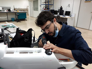
At this stage of the task, it is important to practice the drilling techniques to make sure the alignment with the fuselage is 90 degrees and at the center of the marked location. How I did do it?! I used a 3 mm balsa-wood sheet to do multiple trials and bring confidence before drilling the actual engine mount.
This was the moment of excitement to drill the actual wooden disk.
A sanding sheet was used to sand the two, 3 cm wooden roods, to get rid of the accumulated dust and stains.
Using a G-clamp to insure the attachement of the wooden-disk at the back of the fuselge until the next day to allow enough time for glue curing. See the following figures to show the clamping process.
Day 5:
Tasks:
- Applying the fairings on the Fin-alignment Tubes cuts for smoother aerodynamic frictions.
- Wing-Fuselage attachment using a driller for screwing the four screws
- Servos actuators assembly
- Fuselage wooden-floor installation
At this day, I have managed to work for four hours on all those components to speed-up the assembly process and save time. See the following figures.
 |
Figure #: The final result after installing the two vertical stabilizers to the main horizontal stabilizer |
Day 6:
Cutting and Fitting of GPS PiXHAWK TR NEO-M8N:
Cutting skills played an important role to fit two of the GPS sensors. More importantly is to place them correctly, poiting them forward toward the flight path parallel to the fuselage. See the photos below.
Cutting and fitting of TF-mini LiDAR Module Laser Radar Sensor:
At this stage, I made a cut to fit the sensor at the bottom of the fuselage. The sensor mst be pointing downward towards the ground, within 12 degrees or exactly 90 degrees. This sensor is used to determine the range and it is used also for obstacle avoidance.
Day 8:
Avionics Set-Up:
The next step is to connect all electrical components such as servos to the main flight controller. Then, using Flysky FS-T6 2.4GHz 6CH Mode 2, with Transmitter and Receiver R6-B to run the system and make sure everything works accordingly.
 |
| Flight Controller Wiring View |
 |
| Placing the avionics on a wooden panel before fitting it inside the fuselage |
 |
| The next step was to test the electrical components using FLYSKY and a 6 Channels receiver |
 |
| This is another view after connecting all wires to the flight controller |
Day 9:
Soldring and Structure Panel's adhesive tapes:
The Buzzer is an eletric chip that creates sounds as an alert or an indication of the flight controller's status especially when the power is switched on. Here are some photos of soldring the chip's wire and cover it with an isolator tap to avoid tochings between the wires.
Day 10:
Mission Planner Set-Up:
The software is called "Mission Planner" which is used to program the flight controller such as setting the attitudes, linking the sensors and servos to certain inputs, defining the sides, and getting the position defined with the help of GPS sensors.
Day 11:
Pitot-Tubes Components Fabrications and Installations:
Day 12:
Practicle Solutions:
Measuring the speed of a Fixed-Wing UAV requires the use of a small Pitot tube, however, this also means that the external attachment needs to be an aerodynamically less turbulent and lower drag. Also, the internal Pitot tubes should be aligned using my personal dual-holes clamp to save more space.
Day 13:
Antenna's Fins Design and Installations:
Day 14:
Improvements and Multi-Experiments 3D Modeling:
The photos here show the red slider clamp to fix the avionic's panel from moving during flight. It was designed and customized based on the slider design of the SKY HUNTER.
Day 15: Organization and alignment
The photos show my personal design of what I call as "the a dual-holes clamp" using a 3D printer to align the pito-tupes hoses and other wires for organization and better oriantation on the avionic's panel.
This is a pre-flight check to make sure all controllers and structural components are in good condition.
Here is a quick video for the maiden flight.
Take-off:
Landing:
Thank you for watching. This page will be saved for further usages as a reference for educational purposes.


.jpg)
.jpg)
.jpg)
.jpg)
.jpg)


.jpg)


