-Fixed-Wing UAV Assembly Process-
Introduction:
Assembling a Fixed-Wing UAV airplane model is a learning journey toward real aerospace applications for aerospace engineering students. It is an essential start to do hands-on work to give some tangible feelings of practicality; however, it depends on the level of commitment, discipline style, and the amount of reading relevant topics over the coming years. Hope you will enjoy a different taste in this blog.
Objective:
This post is aimed to show the progress of my contributions to a SKY HUNTER (SKH), UAV, project under University Sains Malaysian, or USM, staff for an industrial application.
Work Flow Begins:
Day 1:
1. Unboxing:
It is important to carefully unbox the UAV parts to avoid damaging the aerodynamic components such as the main wings, fuselage, and the vertical and horizontal stabilizers. Therfore, choosing the correct cutting tool and removing the sides of the box to unload the parts gentally on a clean table. See figure 1.
 |
Figure 1: The SKH UAV inside the box
|
 |
Figure 2: Using my cutting pen to open the sides of the box
|
2. Labeling and Notes Taking:
It depends on the person, this step can be helpful for those who take the time to read a catalog of an RC airplane for instructions and discipline. The parts can be given numbers and short names for easier future tracking, this will help you if you are an aerospace engineer in some of the Aerospace industries. Take notes from previous experts from YouTube or books for easier instructions and techniques in assembly.
3. Parts on a Table! :
 |
Figure 3: Those two brushes of sizes 2 and 8 are to be used for gluing the parts during the assembly of the fuselage, two main wings, and other parts. |
After opening the box correctly, gentally take each part outside on a clean table and make sure they are layed safely to avoid scratching the surfaces of the parts especially the wings.

|
Figure 4: Those are the main components after unboxing all of the parts of SKH UAV and labeling them in my notebook.
 | | Figure 5: Showing some avionics components: (Left-Right: GPS/Compass NEO-M8N, Lider, Buzzer, Aileron control wire, and a receiver with 2 antennas) |
|
The speed controller and other avionics components will be shown in the next coming days as the progress goes on.
4. Personal Notebook:
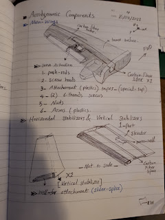
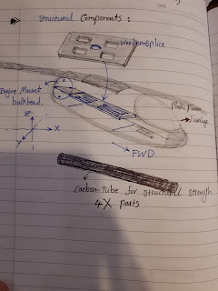
Some of my personal styles of learning about the UAV components and their assembly. It is important for me to visiualize and view some sides of the UAV for future aircraft design projects. This technique has been very helpful for me to train my brain how to use imaginations on designing and airplane before even drawing it on a paper or a software.
I love to draw some sections from different angles to visualize the assembly and improve my drawing skills with those angles. Here some of them in the next figures.
Day 2:1. Fuselage Assembly:
I have used the liquid glue with the brushes to spread the liquid on the sides of the fuselage's pair sides, two plastic splicers. Then, I used 4 nuts and 4 of the (20-threds) long screws with 4 plactic washers to install the two sides of the fuselage section. See figures 10 - 13.
2. Some Remarks:
At this stage, it is important to glue the outer sides of the nuts before placing them inside the extruded hole for firm installations with the main wings later on.

 | Figure 17: Apply wisely some load on the fuselage, using any available objects, to firmly attach the sides and avoid gaps.
|
Day 3:1. Main Wings Assembly:
 | | Figure 18: Applying the glue using the brush is a good technique to minimize the amount of glue |
At this stage, I am assembling the main wings using the Carbon-Fiber cylindrical tubes and cubical spars based on their location on the wings for stiffness and support of internal and external loads.
 | Figure 19: Using a brush with size 8 to paint the main spar's bay to stick the Carbon-fiber cylindrical spar and the foam cover. Bottom view of the right-wing.
|

Figure 20: Applying the glue at the cut area using the brush before placing the CF spar.
 | Figure 21: Carbon-fiber Square spars with different sizes depending on their positions in each wing. It comes in 4 pairs.
|
| |

| | Figure 22: Holding the right-wing after installing the Carbon fiber cylindrical spar and the square spars. |
2. Fin Alignment Guide Tubes:
There are two main fin-tubes that are made out of plastic. There are used for alignment of the empennage components: Horizontal and vertical stabilizers. Here I have assembled the components on the following figures:
| |
|
3. Remarks on Main Wing's mating tolerance:
At this stage, the wings' roots attachment showed 2 mm gaps, which is not prefered during flight and air will go inside the wing box and might cause minor structure damages at high speed. Thus, I had to sand the roots and make sure no gaps are there using sanding sheets and cutting knife. See the photos below.
4. Attachments of vertical and horizontal stabilizers:

| Figure #: A closer view after sticking the CF spar in the slot and leaving the free side empty for the puchrod
|

|
| Figure #: The view after placing the CF spars in the slots |
|
|
|









.jpg)
.jpg)
.jpg)
.jpg)
.jpg)


